


Description
Note: † Grooved Cone (X) is predominantly used for Wire Braid (e.g. GSWB, TCWB), Steel Tape Armour (STA, DSTA) and Aluminium Strip Armour (ASA) but is also suitable for Single Wire Armour (SWA), Aluminium Wire Armour (AWA) and Pliable Wire Armour (PWA) if the range is outside that of the Stepped Cone (W). Note: Grooved Cone (X) dimensions shown in the Cable Gland Selection Table below are for a double wire strand of braid armour cables. Tapes can also be doubled over. For cables that have only a single layer of armour such as SWA the clamping range should be used as shown in the table below. Stepped (W) Cone is suitable for Single Wire Armour (SWA), or Aluminium Wire Armour (AWA) cables. CMP E1FU
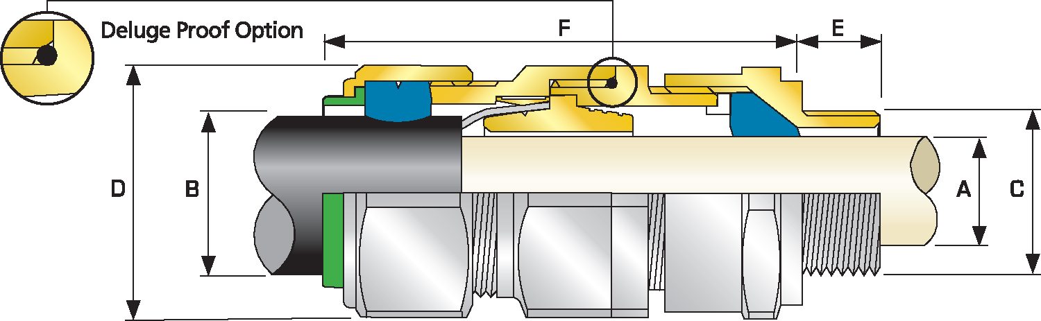
| Cable Gland Size | Available Entry Threads ‘C’ (Alternate Metric Thread Lengths Available) | Cable Bedding Diameter ‘A’ |
Overall Cable Diameter ‘B’ |
Armour Range | Across Flats ‘D’ |
Across Corners ‘D’ |
Protrusion Length ‘F’ |
Combined Ordering Reference (*Brass Metric) |
Shroud | Cable Gland Weight (Kgs) |
|||||||||||
| Standard | Option | Grooved Cone (X) |
Stepped Cone (W) | ||||||||||||||||||
| Metric | Thread Length (Metric) ‘E’ | NPT | Thread Length (NPT) ‘E’ |
NPT | Min | Max | Min | Max | Min | Max | Min | Max | Max | Max | Size | Type | Ordering Suffix |
||||
| 20S16 | M20 | 15.0 | ½” | 19.9 | ¾” | 3.1 | 8.6 | 6.1 | 13.1 | 0.3 | 1.0 | 0.8 | 1.25 | 24.0 | 26.4 | 72.5 | 20S16 | E1FU | 1RA | PVC04 | 0.16 |
| 20S | M20 | 15.0 | ½” | 19.9 | ¾” | 6.1 | 11.6 | 9.5 | 15.9 | 0.3 | 1.0 | 0.8 | 1.25 | 24.0 | 26.4 | 70.0 | 20S | E1FU | 1RA | PVC04 | 0.15 |
| 20 | M20 | 15.0 | ½” | 19.9 | ¾” | 6.5 | 13.9 | 12.5 | 20.9 | 0.4 | 1.0 | 0.8 | 1.25 | 30.5 | 33.6 | 73.0 | 20 | E1FU | 1RA | PVC06 | 0.21 |
| 25S | M25 | 15.0 | ¾” | 20.2 | 1″ | 11.1 | 19.9 | 14.0 | 22.0 | 0.4 | 1.2 | 1.25 | 1.6 | 37.5 | 41.3 | 89.0 | 25S | E1FU | 1RA | PVC09 | 0.33 |
| 25 | M25 | 15.0 | ¾” | 20.2 | 1″ | 11.1 | 19.9 | 18.2 | 26.2 | 0.4 | 1.2 | 1.25 | 1.6 | 37.5 | 41.3 | 89.0 | 25 | E1FU | 1RA | PVC09 | 0.33 |
| 32 | M32 | 15.0 | 1″ | 25.0 | 1 ¼” | 17.0 | 26.2 | 23.7 | 33.9 | 0.4 | 1.2 | 1.6 | 2.0 | 46.0 | 50.6 | 86.0 | 32 | E1FU | 1RA | PVC11 | 0.43 |
| 40 | M40 | 15.0 | 1 ¼” | 25.6 | 1 ½” | 22.0 | 32.1 | 27.9 | 40.4 | 0.4 | 1.6 | 1.6 | 2.0 | 55.0 | 60.5 | 90.0 | 40 | E1FU | 1RA | PVC15 | 0.62 |
| 50S | M50 | 15.0 | 1 ½” | 26.1 | 2″ | 29.5 | 38.1 | 35.2 | 46.7 | 0.4 | 1.6 | 2.0 | 2.5 | 60.0 | 66.0 | 91.0 | 50S | E1FU | 1RA | PVC18 | 0.75 |
| 50 | M50 | 15.0 | 2″ | 26.9 | 2 ½” | 35.6 | 44.0 | 40.4 | 53.0 | 0.6 | 1.6 | 2.0 | 2.5 | 70.1 | 77.1 | 95.0 | 50 | E1FU | 1RA | PVC21 | 0.95 |
| 63S | M63 | 15.0 | 2″ | 26.9 | 2 ½” | 40.1 | 49.9 | 45.6 | 59.4 | 0.6 | 1.6 | 2.0 | 2.5 | 75.0 | 82.5 | 102.0 | 63S | E1FU | 1RA | PVC23 | 1.34 |
| 63 | M63 | 15.0 | 2 ½” | 39.9 | 3″ | 47.2 | 55.9 | 54.6 | 65.8 | 0.6 | 1.6 | 2.0 | 2.5 | 80.0 | 88.0 | 104.0 | 63 | E1FU | 1RA | PVC25 | 1.34 |
| 75S | M75 | 15.0 | 2 ½” | 39.9 | 3″ | 52.8 | 61.9 | 59.0 | 72.0 | 0.6 | 1.6 | 2.0 | 2.5 | 90.0 | 99.0 | 115.0 | 75S | E1FU | 1RA | PVC28 | 2.11 |
| 75 | M75 | 15.0 | 3″ | 41.5 | 3 ½” | 59.1 | 67.9 | 66.7 | 78.4 | 0.6 | 1.6 | 2.5 | 3.0 | 100.0 | 110.0 | 117.0 | 75 | E1FU | 1RA | PVC30 | 2.42 |
| 90 | M90 | 24.0 | 3 ½” | 42.8 | 4″ | 66.6 | 78.6 | 76.2 | 90.3 | 0.8 | 1.6 | 3.15 | 4.0 | 114.3 | 125.4 | 147.0 | 90 | E1FU | 1RA | PVC32 | 4.21 |
| 100 | M100 | 24.0 | 3 ½” | 42.8 | 4″ | 76.0 | 90.9 | 86.1 | 101.4 | 0.8 | 1.6 | 3.15 | 4.0 | 123.0 | 135.3 | 140.0 | 100 | E1FU | 1RA | LSF33 | 4.45 |
| 115 | M115 | 24.0 | 4″ | 44.0 | 5″ | 86.0 | 97.9 | 101.5 | 110.2 | 0.8 | 1.6 | 3.15 | 4.0 | 133.4 | 146.7 | 162.0 | 115 | E1FU | 1RA | LSF34 | 6.19 |
| 130 | M130 | 24.0 | 5″ | 46.8 | – | 97.0 | 114.9 | 110.2 | 123.2 | 0.8 | 1.6 | 3.15 | 4.0 | 152.4 | 167.6 | 174.0 | 130 | E1FU | 1RA | LSF35 | 8.34 |
| Dimensions displayed in millimeters unless otherwise stated | |||||||||||||||||||||
