


Description
Product Selection Table
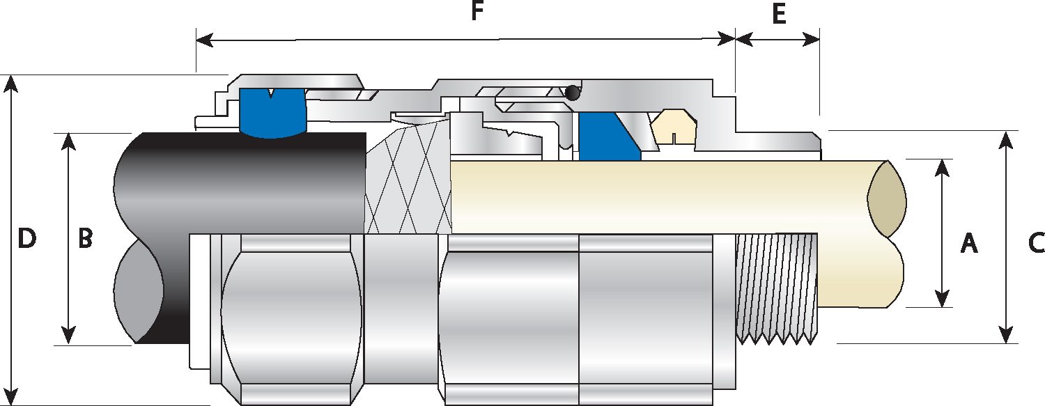
| Cable Gland Size | Available Entry Threads ‘C’ (Alternate Metric Thread Lengths Available) | Cable Bedding Diameter ‘A’ |
Overall Cable Diameter ‘B’ |
Armour Range | Across Flats ‘D’ |
Across Corners ‘D’ |
Protrusion Length ‘F’ |
Combined Ordering Reference (Stainless Steel Metric) |
Shroud | Cable Gland Weight (Kgs) |
|||||||||||
| Standard | Option | Grooved Cone (X) | Stepped Cone (W) | ||||||||||||||||||
| Metric | Thread Length (Metric) ‘E’ | NPT | Thread Length (NPT) ‘E’ |
NPT | Min | Max | Min | Max | Min | Max | Min | Max | Max | Max | Size | Type | Ordering Suffix |
||||
| 20S16 | M20 | 15.0 | ½’ | 19.9 | ¾” | 3.1 | 8.6 | 6.1 | 13.1 | 0.3 | 1.0 | 0.8 | 1.25 | 24.0 | 26.4 | 57.3 | 20S16 | TE1FU | 1RA4 | PVC04 | 0.15 |
| 20S | M20 | 15.0 | ½’ | 19.9 | ¾” | 6.1 | 11.6 | 9.5 | 15.9 | 0.3 | 1.0 | 0.8 | 1.25 | 24.0 | 26.4 | 57.3 | 20S | TE1FU | 1RA4 | PVC04 | 0.15 |
| 20 | M20 | 15.0 | ½’ | 19.9 | ¾” | 6.5 | 13.9 | 12.5 | 20.9 | 0.4 | 1.0 | 0.8 | 1.25 | 30.5 | 33.6 | 61.2 | 20 | TE1FU | 1RA4 | PVC06 | 0.23 |
| 25S | M25 | 15.0 | ¾’ | 20.2 | 1″ | 11.1 | 19.9 | 14.0 | 22.0 | 0.4 | 1.2 | 1.25 | 1.6 | 37.5 | 41.3 | 74.0 | 25S | TE1FU | 1RA4 | PVC09 | 0.34 |
| 25 | M25 | 15.0 | ¾’ | 20.2 | 1″ | 11.1 | 19.9 | 18.2 | 26.2 | 0.4 | 1.2 | 1.25 | 1.6 | 37.5 | 41.3 | 74.0 | 25 | TE1FU | 1RA4 | PVC09 | 0.34 |
| 32 | M32 | 15.0 | 1′ | 25.0 | 1 ¼” | 17.0 | 26.2 | 23.7 | 33.9 | 0.4 | 1.2 | 1.6 | 2.0 | 46.0 | 50.6 | 78.2 | 32 | TE1FU | 1RA4 | PVC11 | 0.55 |
| 40 | M40 | 15.0 | 1 ¼’ | 25.6 | 1 ½” | 22.0 | 32.1 | 27.9 | 40.4 | 0.4 | 1.6 | 1.6 | 2.0 | 55.0 | 60.5 | 81.6 | 40 | TE1FU | 1RA4 | PVC15 | 0.79 |
| 50S | M50 | 15.0 | 1 ½’ | 26.1 | 2″ | 29.5 | 38.1 | 35.2 | 46.7 | 0.4 | 1.6 | 2.0 | 2.5 | 60.0 | 66.0 | 88.1 | 50S | TE1FU | 1RA4 | PVC18 | 1.00 |
| 50 | M50 | 15.0 | 2′ | 26.9 | 2 ½” | 35.6 | 44.0 | 40.4 | 53.0 | 0.6 | 1.6 | 2.0 | 2.5 | 70.1 | 77.1 | 91.2 | 50 | TE1FU | 1RA4 | PVC21 | 1.37 |
| 63S | M63 | 15.0 | 2′ | 26.9 | 2 ½” | 40.1 | 49.9 | 45.6 | 59.4 | 0.6 | 1.6 | 2.0 | 2.5 | 75.0 | 82.4 | 90.5 | 63S | TE1FU | 1RA4 | PVC23 | 1.50 |
| 63 | M63 | 15.0 | 2 ½’ | 39.9 | 3″ | 47.2 | 55.9 | 54.6 | 65.8 | 0.6 | 1.6 | 2.0 | 2.5 | 80.0 | 88.0 | 90.3 | 63 | TE1FU | 1RA4 | PVC25 | 1.56 |
| 75S | M75 | 15.0 | 2 ½’ | 39.9 | 3″ | 52.8 | 61.9 | 59.0 | 72.0 | 0.6 | 1.6 | 2.0 | 2.5 | 90.0 | 99.0 | 104.7 | 75S | TE1FU | 1RA4 | PVC28 | 2.45 |
| 75 | M75 | 15.0 | 3′ | 41.5 | 3 ½” | 59.1 | 67.9 | 66.7 | 78.4 | 0.6 | 1.6 | 2.5 | 3.0 | 100.0 | 110.0 | 110.8 | 75 | TE1FU | 1RA4 | PVC30 | 3.15 |
| 90 | M90 | 24.0 | 3 ½’ | 42.8 | 4″ | 66.6 | 78.6 | 76.2 | 90.3 | 0.8 | 1.6 | 3.15 | 4.0 | 115.0 | 126.5 | 135.5 | 90 | TE1FU | 1RA4 | PVC32 | 4.62 |
| 100 | M100 | 24.0 | 3 ½’ | 42.8 | 4″ | 76.0 | 90.9 | 86.1 | 101.4 | 0.8 | 1.6 | 3.15 | 4.0 | 127.0 | 139.7 | 126.8 | 100 | TE1FU | 1RA4 | LSF33 | 4.95 |
| 115 | M115 | 24.0 | 4″ | 44.0 | 5″ | 86.0 | 97.9 | 101.5 | 110.2 | 0.8 | 1.6 | 3.15 | 4.0 | 138.0 | 151.8 | 157.5 | 115 | TE1FU | 1RA4 | LSF34 | 7.60 |
| 130 | M130 | 24.0 | 5″ | 46.8 | – | 97.0 | 114.9 | 110.2 | 123.2 | 0.8 | 1.6 | 3.15 | 4.0 | 157.0 | 172.7 | 164.5 | 130 | TE1FU | 1RA4 | LSF35 | 8.73 |
| Dimensions displayed in millimeters unless otherwise stated | |||||||||||||||||||||
