


Description
Description
Please note the following installation requirements:
1) Where explosionproof enclosures are being used the TMC must be installed with an approved pouring or compound sealing fitting. In Division 2 locations the TMC can be fitted directly to an enclosure which has no source of ignition in accordance with NEC/CEC requirements.
2) Glands with NPT entry threads are suitable for both Divisions and Zones.
3) Glands with Metric entry threads are suitable for Zones only unless fitted with an approved NPT male adaptor in accordance with CEC requirements.
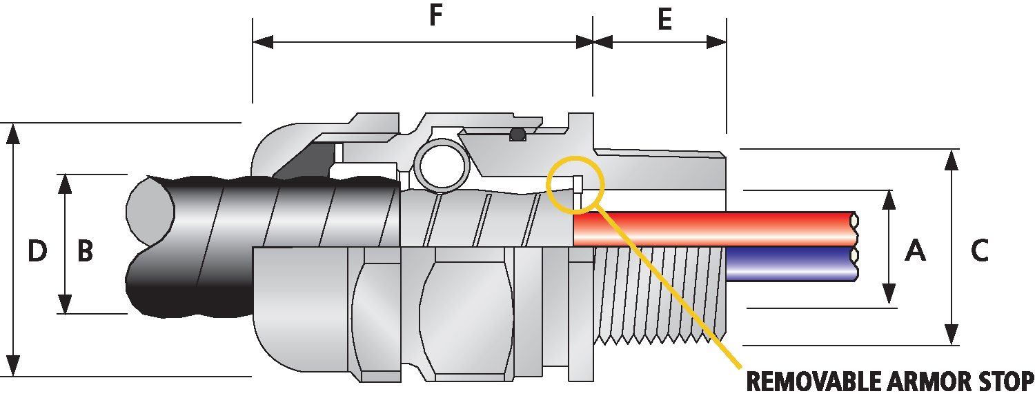
TMC Connector Product Selection Table
| Order Reference (NPT) |
Entry Thread ‘C’ |
Minimum Thread Length ‘E’ |
Minimum Thread Length ‘E’ |
Cable Armor Diameter ‘A’ | Cable Jacket Diameter ‘B’ | Nominal Assembly Length ‘F’ | Max | Shroud | Weight (Kgs) |
||||||||
| End Stop In | End Stop Out | ||||||||||||||||
| Aluminum | Nickel Plated Brass | Stainless Steel | NPT | Metric | NPT | Metric | Min | Max | Min | Max | Min | Max | Across Flats ‘D’ |
Across Corners ‘D’ |
|||
| TMC050SA | TMC050SNB | TMC050SSS | ½’ | M20 | 19.8 | 15.0 | No Stop | No Stop | 8.6 | 12.7 | 8.9 | 14.0 | 46.5 | 30.5 | 33.5 | PVC06 | 0.22 |
| TMC050A | TMC050NB | TMC050SS | ½’ | M20 | 19.8 | 15.0 | No Stop | No Stop | 13.0 | 17.0 | 11.2 | 20.1 | 52.3 | 36.1 | 39.6 | PVC09 | 0.28 |
| TMC075A | TMC075NB | TMC075SS | ¾’ | M25 | 20.3 | 15.0 | 15.0 | 19.3 | 19.3 | 23.4 | 17.0 | 26.4 | 53.1 | 40.9 | 45.2 | PVC10 | 0.33 |
| TMC100A | TMC100NB | TMC100SS | 1′ | M32 | 24.9 | 15.0 | 19.8 | 24.6 | 24.6 | 29.2 | 22.1 | 32.3 | 56.9 | 50.0 | 55.1 | PVC13 | 0.50 |
| TMC125A | TMC125NB | TMC125SS | 1 ¼’ | M40 | 25.7 | 15.0 | 27.4 | 31.2 | 31.2 | 35.3 | 29.5 | 38.1 | 56.4 | 55.1 | 60.5 | PVC15 | 0.59 |
| TMC150A | TMC150NB | TMC150SS | 1 ½’ | M50 | 26.2 | 15.0 | 33.5 | 37.1 | 37.1 | 41.1 | 35.6 | 44.2 | 58.7 | 59.9 | 66.0 | PVC18 | 0.69 |
| TMC200SA | TMC200SNB | TMC200SSS | 2′ | M50 | 26.9 | 15.0 | 38.4 | 42.7 | 42.7 | 47.0 | 40.1 | 50.0 | 64.0 | 70.1 | 77.0 | PVC21 | 1.20 |
| TMC200A | TMC200NB | TMC200SS | 2′ | M63 | 26.9 | 15.0 | 45.0 | 49.0 | 49.0 | 53.1 | 47.2 | 56.1 | 63.2 | 74.9 | 82.6 | PVC23 | 1.10 |
| TMC250SA | TMC250SNB | TMC250SSS | 2 ½’ | M75 | 39.9 | 15.0 | 52.1 | 54.9 | 54.9 | 58.9 | 52.8 | 62.0 | 69.3 | 80.0 | 88.1 | PVC25 | 1.70 |
| TMC250A | TMC250NB | TMC250SS | 2 ½’ | M75 | 39.9 | 15.0 | 57.2 | 61.2 | 61.2 | 64.8 | 59.2 | 68.1 | 72.1 | 85.1 | 93.5 | PVC27 | 1.60 |
| TMC300A | TMC300NB | TMC300SS | 3′ | M90 | 41.4 | 15.0 | 64.5 | 70.6 | 70.6 | 75.4 | 66.5 | 79.5 | 98.3 | 110.0 | 120.9 | LSF32 | 3.50 |
| TMC350A | TMC350NB | TMC350SS | 3½’ | M100 | 42.9 | 24.1 | 73.9 | 83.6 | 83.6 | 88.6 | 75.9 | 97.3 | 117.6 | 133.4 | 146.8 | LSF34 | 6.70 |
| TMC400A | TMC400NB | TMC400SS | 4′ | M115 | 43.9 | 24.1 | 73.9 | 83.6 | 83.6 | 88.6 | 75.9 | 97.3 | 117.6 | 133.4 | 146.8 | LSF34 | 7.50 |
| Dimensions displayed in millimeters unless otherwise stated | |||||||||||||||||
Part Numbers
| TMC050SNB | TMC050SA |
| TMC050NB | TMC050A |
| TMC075NB | TMC075A |
| TMC100NB | TMC100A |
| TMC125NB | TMC125A |
| TMC150NB | TMC150A |
| TMC200SNB | TMC200SA |
| TMC200NB | TMC200A |
| TMC250SNB | TMC250SA |
| TMC250NB | TMC250A |
| TMC300NB | TMC300A |
| TMC350NB | TMC350A |
| TMC400NB | TMC400A |
