Products > PX2KW Cable Gland
explosive atmosphere steel wire armored swa epoxy gland

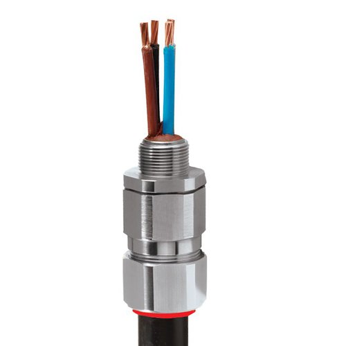
PX2KW Cable Gland
explosive atmosphere steel wire armored swa epoxy gland

Globally Approved, Explosive Atmosphere Barrier Cable Gland

• Metal-to-metal armour clamping
• Direct & remote installation
• Compound barrier type flameproof seal
• Controlled outer ‘load retention’ seal
• Unique OSTG prevents overtightening
• Integral protected deluge seal
• -60°C to +85°C
• Class I Zone 1, 21 and Zone 2, 22 Class I Division 1 & 2 ABCD
• Globally marked, IECEx, ATEX, UL & cCSAus
• EMC tested

For under / oversized armour wires

For all types of Steel & Aluminium Wire Armoured Cables

Description

Technical

Design SpecificationBS 6121:Part 1:1989, IEC 62444, EN 62444
Mechanical Classifications*Impact = Level 8, Retention = Class D
Enclosure ProtectionIK10 to IEC 62262 (20 joules) Brass & Stainless Steel only
Electrical Classifications *Category B
ATEX CertificateSIRA13ATEX1072X, SIRA13ATEX4078X
Code of Protection II 2G, II 1D, Ex d IIC Gb, Ex e IIc Gb, Ex ta IIIC Da
II 3G Ex nR IIC Gc, IM2 Ex d I Mb, Ex e I Mb
Compliance StandardsEN 60079-0,1,7,15,31
IECEx CertificateIECEx SIR 13.0027X, IECEx SIM 14.0008X
Code of ProtectionEx d IIC Gb, Ex e IIC Gb, Ex nR IIC Gc, Ex ta IIIC Da, Ex d I Mb, Ex e I Mb
Compliance StandardsIEC 60079-0,1,7,15,31
cCSAus Certificate2288626
CSAus Code of Protection***Class I, Div. 2 Groups A, B, C and D; Class II, Div. 2 Groups F and G; Class III, Div. 2; Type 4X: Oil
Resistant II:
Class I, Zone 1 AEx d IIC Gb, AEx e IIC Gb, Class I, Zone 2 AEx nR IIC Gc, Class I, Zone 20 AEx ta
IIIC Da
cCSA Code of Protection***Class I, Div. 2 Groups A, B, C and D; Class II, Div. 2 Groups F and G; Class III, Div. 2; Type 4X: Oil
Resistant II:
Ex d IIC Gb, Ex e IIC Gb, Ex nR IIC Gc, Ex ta IIIC Da
Compliance StandardsCAN/CSA-C22.2 No 0,18,25,30,94,174, CAN/CSA-E60079-0,1,7,15,31 CAN/CSA-E61241-1-1 Part
1-1, ANSI/UL 514B Ed 5, ANSI/UL 50 Ed 11, ANSI/UL 2225 Ed 4, UL60079
UL Certificate (20s16 – 100)E161256C
Code of ProtectionClass I, Div 2, Groups A,B,C,D; Class II, Div 2, Groups F,G
Compliance StandardsUL 2225, CSA C22.2 No 174, UL 514B, CSA C22.2 No 18
EAC CertificateTC RU C-GB.AA87.B.00487
UkrSEPROUA.TR.047.C.0644-15
KCC Certificate14-GA4BO-0252X
CCOE / PESO (India) CertificateP333688
NEPSI CertificateGYJ13.1140X, GYJ13.1282X
INMETRO ApprovalTÜV 12.2073X
RETIE Approval03866
Marine ApprovalsLRS: 01/00172, DNV: TAE00000Y, ABS: 14-LD234401A-4-PDA, BV: 43180/A1BV
Ingress Protection Rating **IP66, IP67 & IP68**
Deluge Protection ComplianceDTS01 : 91
Cable Gland MaterialElectroless Nickel Plated Brass, Brass, Stainless Steel, Aluminium
Seal MaterialCMP SOLO LSF Halogen Free Thermoset Elastomer / Epoxy Barrier Compound
Cable TypeSingle Wire Armour (SWA), Aluminium Wire Armour (AWA)***
Armour ClampingDetachable Compound Tube / Cone & AnyWay Universal Clamping Ring
Sealing TechniqueUnique CMP ‘LRS’ Outer Seal (Load Retention Seal)
Sealing Area(s)Inner Compound Barrier & Cable Outer Sheath
Optional AccessoriesLocknuts, Earth Tags, Serrated Washers, Entry Thread Seals, Shrouds,Ingress Discs
Optional Installation ToolsSpanners, Armour Former Tool

Product Table

Metric

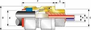
Cable Gland SizeAvailable Entry Threads “C” (Alternate Metric Thread Lengths Available)Number of CoresDiameter Over Conductors
“A”
Cable
Bedding
Diameter
“G”
Overall
Cable
Diameter
“B”
Armour RangeAcross
Flats
“D”
Across
Corners
“D”
Protrusion
Length “F”
Combined Ordering Reference
(*Brass Metric)
ShroudCable
Gland
Weight
(Kgs)
StandardOption
MetricThread Length (Metric) “E”NPTThread Length
(NPT) “E”
NPTMaxMinMaxMinMaxMaxMaxSizeTypeOrdering
Suffix
20S16M2015.0½”19.9¾”1111.711.76.113.10.81.2530.533.662.020S16PX2KW1RAPVC060.24
20SM2015.0½”19.9¾”1111.711.79.515.90.81.2530.533.662.020SPX2KW1RAPVC060.23
20M2015.0½”19.9¾”1112.612.912.520.90.81.2530.533.663.020PX2KW1RAPVC060.24
25SM2515.0¾”20.21″2117.517.914.022.01.251.637.541.369.525SPX2KW1RAPVC090.37
25M2515.0¾”20.21″2117.517.918.226.21.251.637.541.369.525PX2KW1RAPVC090.37
32M3215.01″25.01 ¼”3823.623.923.733.91.62.046.050.675.032PX2KW1RAPVC110.57
40M4015.01 ¼”25.61 ½”5930.030.327.940.41.62.055.060.575.040PX2KW1RAPVC150.80
50SM5015.01 ½”26.12″8936.636.935.246.72.02.560.066.077.050SPX2KW1RAPVC180.90
50M5015.02″26.92 ½”8941.041.340.453.02.02.570.177.177.150PX2KW1RAPVC211.19
63SM6315.02″26.92 ½”11547.948.445.659.42.02.575.082.579.763SPX2KW1RAPVC231.39
63M6315.02 ½”39.93″11553.754.054.665.82.02.580.088.080.363PX2KW1RAPVC251.41
75SM7515.02 ½”39.93″14059.960.259.072.02.02.590.099.086.875SPX2KW1RAPVC282.09
75M7515.03″41.53 ½”14064.264.266.778.42.53.0100.0110.088.375PX2KW1RAPVC302.54
90M9024.03 ½”42.84″20075.375.676.290.33.154.0115.0126.5102.190PX2KW1RAPVC323.71
100M10024.03 ½”42.84″20085.685.986.1101.43.154.0127.0139.7114.0100PX2KW1RALSF334.81
Dimensions displayed in millimeters unless otherwise stated

Imperial

Cable Gland SizeAvailable Entry Threads “C” (Alternate Metric Thread Lengths Available)Number of CoresDiameter Over Conductors
“A”
Cable
Bedding
Diameter
“G”
Overall
Cable
Diameter
“B”
Armour RangeAcross
Flats
“D”
Across
Corners
“D”
Protrusion
Length “F”
Combined Ordering Reference
(*Brass Metric)
ShroudCable
Gland
Weight
(Ozs)
StandardOption
MetricThread Length (Metric) “E”NPTThread Length
(NPT) “E”
NPTMaxMinMaxMinMaxMaxMaxSizeTypeOrdering
Suffix
20S16M200.59½”0.78¾”110.460.460.240.520.030.051.201.322.4420S16PX2KW1RAPVC068.47
20SM200.59½”0.78¾”110.460.460.370.630.030.051.201.322.4420SPX2KW1RAPVC068.11
20M200.59½”0.78¾”110.500.510.490.820.030.051.201.322.4820PX2KW1RAPVC068.47
25SM250.59¾”0.801″210.690.700.550.870.050.061.481.632.7425SPX2KW1RAPVC0913.05
25M250.59¾”0.801″210.690.700.721.030.050.061.481.632.7425PX2KW1RAPVC0913.05
32M320.591″0.981 ¼”380.930.940.931.330.060.081.811.992.9532PX2KW1RAPVC1120.11
40M400.591 ¼”1.011 ½”591.181.191.101.590.060.082.172.382.9540PX2KW1RAPVC1528.22
50SM500.591 ½”1.032″891.441.451.391.840.080.102.362.603.0350SPX2KW1RAPVC1831.75
50M500.592″1.062 ½”891.611.631.592.090.080.102.763.043.0450PX2KW1RAPVC2141.98
63SM630.592″1.062 ½”1151.891.911.802.340.080.102.953.253.1463SPX2KW1RAPVC2349.03
63M630.592 ½”1.573″1152.112.132.152.590.080.103.153.463.1663PX2KW1RAPVC2549.74
75SM750.592 ½”1.573″1402.362.372.322.830.080.103.543.903.4275SPX2KW1RAPVC2873.72
75M750.593″1.633 ½”1402.532.532.633.090.100.123.944.333.4875PX2KW1RAPVC3089.60
90M900.943 ½”1.694″2002.962.983.003.560.120.164.534.984.0290PX2KW1RAPVC32130.87
100M1000.943 ½”1.694″2003.373.383.393.990.120.165.005.504.49100PX2KW1RALSF33169.67
Dimensions displayed in inches unless otherwise stated

Download Spec Sheet

Download

Technical

Design SpecificationBS 6121:Part 1:1989, IEC 62444, EN 62444
Mechanical Classifications*Impact = Level 8, Retention = Class D
Enclosure ProtectionIK10 to IEC 62262 (20 joules) Brass & Stainless Steel only
Electrical Classifications *Category B
ATEX CertificateSIRA13ATEX1072X, SIRA13ATEX4078X
Code of Protection II 2G, II 1D, Ex d IIC Gb, Ex e IIc Gb, Ex ta IIIC Da
II 3G Ex nR IIC Gc, IM2 Ex d I Mb, Ex e I Mb
Compliance StandardsEN 60079-0,1,7,15,31
IECEx CertificateIECEx SIR 13.0027X, IECEx SIM 14.0008X
Code of ProtectionEx d IIC Gb, Ex e IIC Gb, Ex nR IIC Gc, Ex ta IIIC Da, Ex d I Mb, Ex e I Mb
Compliance StandardsIEC 60079-0,1,7,15,31
cCSAus Certificate2288626
CSAus Code of Protection***Class I, Div. 2 Groups A, B, C and D; Class II, Div. 2 Groups F and G; Class III, Div. 2; Type 4X: Oil
Resistant II:
Class I, Zone 1 AEx d IIC Gb, AEx e IIC Gb, Class I, Zone 2 AEx nR IIC Gc, Class I, Zone 20 AEx ta
IIIC Da
cCSA Code of Protection***Class I, Div. 2 Groups A, B, C and D; Class II, Div. 2 Groups F and G; Class III, Div. 2; Type 4X: Oil
Resistant II:
Ex d IIC Gb, Ex e IIC Gb, Ex nR IIC Gc, Ex ta IIIC Da
Compliance StandardsCAN/CSA-C22.2 No 0,18,25,30,94,174, CAN/CSA-E60079-0,1,7,15,31 CAN/CSA-E61241-1-1 Part
1-1, ANSI/UL 514B Ed 5, ANSI/UL 50 Ed 11, ANSI/UL 2225 Ed 4, UL60079
UL Certificate (20s16 – 100)E161256C
Code of ProtectionClass I, Div 2, Groups A,B,C,D; Class II, Div 2, Groups F,G
Compliance StandardsUL 2225, CSA C22.2 No 174, UL 514B, CSA C22.2 No 18
EAC CertificateTC RU C-GB.AA87.B.00487
UkrSEPROUA.TR.047.C.0644-15
KCC Certificate14-GA4BO-0252X
CCOE / PESO (India) CertificateP333688
NEPSI CertificateGYJ13.1140X, GYJ13.1282X
INMETRO ApprovalTÜV 12.2073X
RETIE Approval03866
Marine ApprovalsLRS: 01/00172, DNV: TAE00000Y, ABS: 14-LD234401A-4-PDA, BV: 43180/A1BV
Ingress Protection Rating **IP66, IP67 & IP68**
Deluge Protection ComplianceDTS01 : 91
Cable Gland MaterialElectroless Nickel Plated Brass, Brass, Stainless Steel, Aluminium
Seal MaterialCMP SOLO LSF Halogen Free Thermoset Elastomer / Epoxy Barrier Compound
Cable TypeSingle Wire Armour (SWA), Aluminium Wire Armour (AWA)***
Armour ClampingDetachable Compound Tube / Cone & AnyWay Universal Clamping Ring
Sealing TechniqueUnique CMP ‘LRS’ Outer Seal (Load Retention Seal)
Sealing Area(s)Inner Compound Barrier & Cable Outer Sheath
Optional AccessoriesLocknuts, Earth Tags, Serrated Washers, Entry Thread Seals, Shrouds,Ingress Discs
Optional Installation ToolsSpanners, Armour Former Tool

Product Table

Metric

Cable Gland SizeAvailable Entry Threads “C” (Alternate Metric Thread Lengths Available)Number of CoresDiameter Over Conductors
“A”
Cable
Bedding
Diameter
“G”
Overall
Cable
Diameter
“B”
Armour RangeAcross
Flats
“D”
Across
Corners
“D”
Protrusion
Length “F”
Combined Ordering Reference
(*Brass Metric)
ShroudCable
Gland
Weight
(Kgs)
StandardOption
MetricThread Length (Metric) “E”NPTThread Length
(NPT) “E”
NPTMaxMinMaxMinMaxMaxMaxSizeTypeOrdering
Suffix
20S16M2015.0½”19.9¾”1111.711.76.113.10.81.2530.533.662.020S16PX2KW1RAPVC060.24
20SM2015.0½”19.9¾”1111.711.79.515.90.81.2530.533.662.020SPX2KW1RAPVC060.23
20M2015.0½”19.9¾”1112.612.912.520.90.81.2530.533.663.020PX2KW1RAPVC060.24
25SM2515.0¾”20.21″2117.517.914.022.01.251.637.541.369.525SPX2KW1RAPVC090.37
25M2515.0¾”20.21″2117.517.918.226.21.251.637.541.369.525PX2KW1RAPVC090.37
32M3215.01″25.01 ¼”3823.623.923.733.91.62.046.050.675.032PX2KW1RAPVC110.57
40M4015.01 ¼”25.61 ½”5930.030.327.940.41.62.055.060.575.040PX2KW1RAPVC150.80
50SM5015.01 ½”26.12″8936.636.935.246.72.02.560.066.077.050SPX2KW1RAPVC180.90
50M5015.02″26.92 ½”8941.041.340.453.02.02.570.177.177.150PX2KW1RAPVC211.19
63SM6315.02″26.92 ½”11547.948.445.659.42.02.575.082.579.763SPX2KW1RAPVC231.39
63M6315.02 ½”39.93″11553.754.054.665.82.02.580.088.080.363PX2KW1RAPVC251.41
75SM7515.02 ½”39.93″14059.960.259.072.02.02.590.099.086.875SPX2KW1RAPVC282.09
75M7515.03″41.53 ½”14064.264.266.778.42.53.0100.0110.088.375PX2KW1RAPVC302.54
90M9024.03 ½”42.84″20075.375.676.290.33.154.0115.0126.5102.190PX2KW1RAPVC323.71
100M10024.03 ½”42.84″20085.685.986.1101.43.154.0127.0139.7114.0100PX2KW1RALSF334.81
Dimensions displayed in millimeters unless otherwise stated

Imperial

Cable Gland SizeAvailable Entry Threads “C” (Alternate Metric Thread Lengths Available)Number of CoresDiameter Over Conductors
“A”
Cable
Bedding
Diameter
“G”
Overall
Cable
Diameter
“B”
Armour RangeAcross
Flats
“D”
Across
Corners
“D”
Protrusion
Length “F”
Combined Ordering Reference
(*Brass Metric)
ShroudCable
Gland
Weight
(Ozs)
StandardOption
MetricThread Length (Metric) “E”NPTThread Length
(NPT) “E”
NPTMaxMinMaxMinMaxMaxMaxSizeTypeOrdering
Suffix
20S16M200.59½”0.78¾”110.460.460.240.520.030.051.201.322.4420S16PX2KW1RAPVC068.47
20SM200.59½”0.78¾”110.460.460.370.630.030.051.201.322.4420SPX2KW1RAPVC068.11
20M200.59½”0.78¾”110.500.510.490.820.030.051.201.322.4820PX2KW1RAPVC068.47
25SM250.59¾”0.801″210.690.700.550.870.050.061.481.632.7425SPX2KW1RAPVC0913.05
25M250.59¾”0.801″210.690.700.721.030.050.061.481.632.7425PX2KW1RAPVC0913.05
32M320.591″0.981 ¼”380.930.940.931.330.060.081.811.992.9532PX2KW1RAPVC1120.11
40M400.591 ¼”1.011 ½”591.181.191.101.590.060.082.172.382.9540PX2KW1RAPVC1528.22
50SM500.591 ½”1.032″891.441.451.391.840.080.102.362.603.0350SPX2KW1RAPVC1831.75
50M500.592″1.062 ½”891.611.631.592.090.080.102.763.043.0450PX2KW1RAPVC2141.98
63SM630.592″1.062 ½”1151.891.911.802.340.080.102.953.253.1463SPX2KW1RAPVC2349.03
63M630.592 ½”1.573″1152.112.132.152.590.080.103.153.463.1663PX2KW1RAPVC2549.74
75SM750.592 ½”1.573″1402.362.372.322.830.080.103.543.903.4275SPX2KW1RAPVC2873.72
75M750.593″1.633 ½”1402.532.532.633.090.100.123.944.333.4875PX2KW1RAPVC3089.60
90M900.943 ½”1.694″2002.962.983.003.560.120.164.534.984.0290PX2KW1RAPVC32130.87
100M1000.943 ½”1.694″2003.373.383.393.990.120.165.005.504.49100PX2KW1RALSF33169.67
Dimensions displayed in inches unless otherwise stated