


Description
Product Selection Table
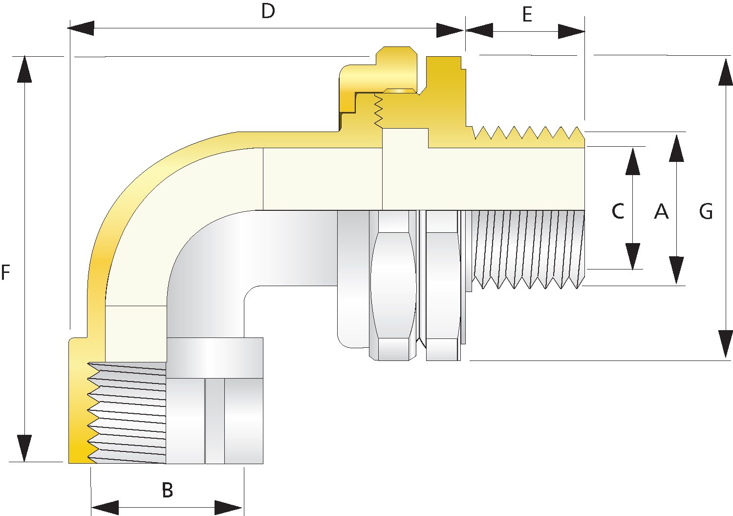
| Metric | NPT | Bore Diameter “‘C”‘ | Max Protrusion Length “D'” | Max Overhang Length ‘”F'” | Across Flats Hex ‘”G'” | Across Corners Ø ‘”G”‘ | Installation Torque (Nm) | Weight (Kgs) | ||||||
| Ordering Reference (Brass, Metric) | Male Forward Thread Size ‘”A'” | Minimum Thread Length “‘E'” | Female Rear Thread Size ‘”B'” | Ordering Reference (Brass, NPT) | Male Forward NPT Thread Size ‘”A'” | Minimum NPT Thread Length “‘E”‘ (in) | Female Rear Thread Size “‘B'” | |||||||
| 789DM2M2 | M20 X 1.5 | 15.0 | M20 X 1.5 | 789DT1T1 | 1/2″ | 0.79 | 1/2″ | 14.3 | 62.9 | 63.8 | 46.0 | 50.6 | 7 | 0.35 |
| 789DM3M3 | M25 X 1.5 | 15.0 | M25 X 1.5 | 789DT2T2 | 3/4″ | 0.80 | 3/4″ | 20.1 | 70.6 | 69.5 | 50.0 | 55.0 | 10 | 0.45 |
| 789DM4M4 | M32 X 1.5 | 15.0 | M32 X 1.5 | 789DT3T3 | 1″ | 0.98 | 1″ | 26.4 | 75.7 | 78.0 | 60.0 | 66.0 | 15 | 0.59 |
| 789DM5M5 | M40 X 1.5 | 15.0 | M40 X 1.5 | 789DT4T4 | 1 1/4″ | 1.01 | 1 14″ | 32.6 | 83.7 | 84.8 | 65.0 | 71.5 | 25 | 0.74 |
| 789DM6M6 | M50 X 1.5 | 15.0 | M50 X 1.5 | 789DT5T5 | 1 1/2″ | 1.03 | 1 1/2″ | 43.0 | 95.9 | 96.3 | 75.0 | 82.5 | 30 | 1.05 |
| 789DM7M7 | M63 X 1.5 | 15.0 | M63 X 1.5 | 789DT6T6 | 2″ | 1.06 | 2″ | 55.0 | 108.8 | 115.1 | 90.2 | 99.2 | 45 | 1.52 |
| All dimensions shown are in millimetres unless otherwise stated | ||||||||||||||
